Simulation and Analysis Projects

All the Simulation Models are beautifully designed in a very smart way to bring the best user experience that you will love.

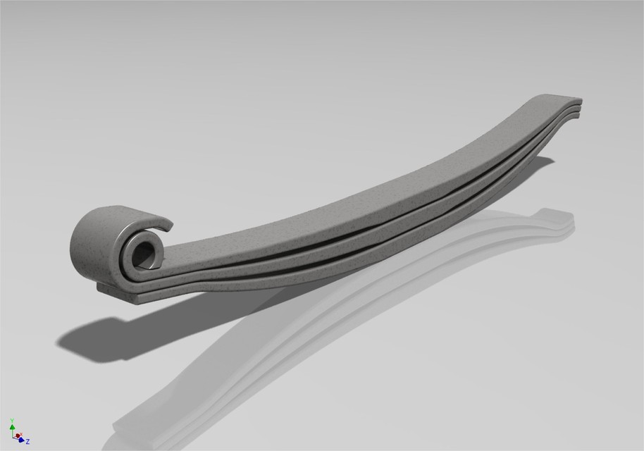
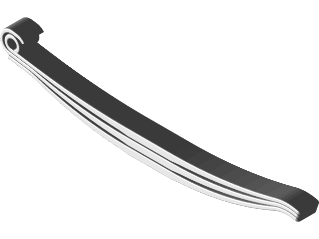
1. Leaf Spring FEA analysis

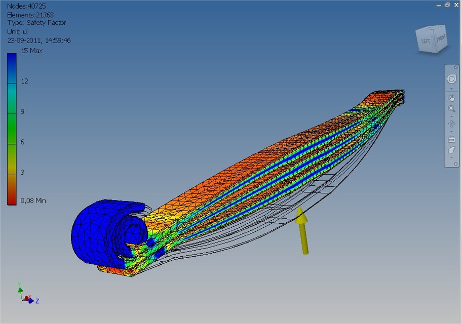
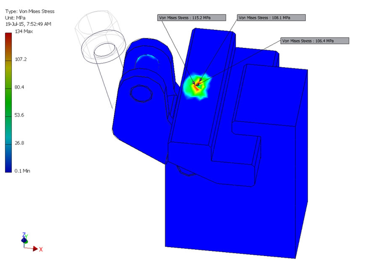
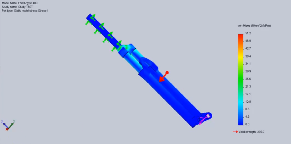
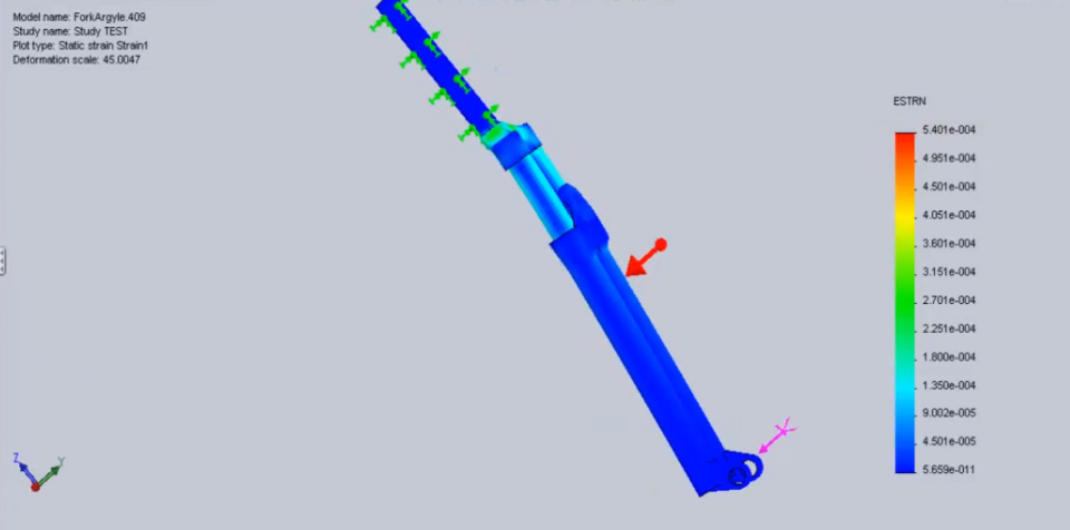
In the FEA analysis environment , a new simulation of the 'Static Analysis' type was created . Since, in this case, all parts of the set slide and interact with each other, the option 'Sliding/No Separation' was selected in the 'Contacts' - 'Default Type' field .


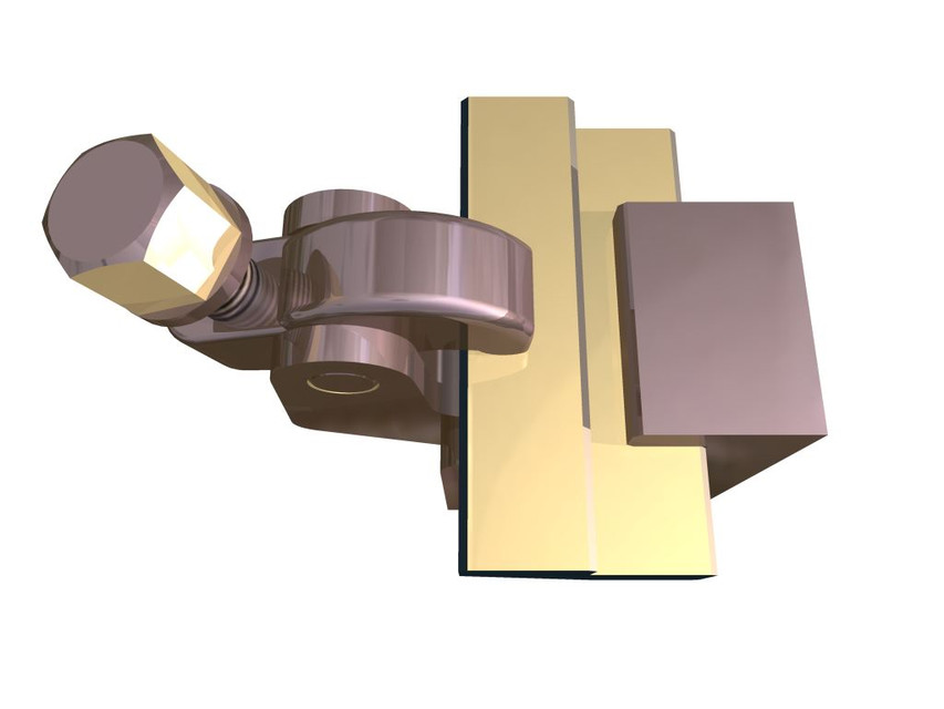
To simulate the operating scenario of this product, three 'Constraints' were applied : A 'Pin' type 'Constraint' on the spring eye, a 'Frictionless' type on the upper blade support area and finally another 'Constraint' 'Frictionless' type on the side of all blades, simply to avoid lateral displacements in the final result.
The applied load was 150 000 N at the bottom of the spring. The results can be seen in the following video:

2. Screw-clamp Stress Analysis

The assembly is a typical part from a clamping device. A „Part” is clamped in a jig device in order to be manufactured. The force is applied by a screw at a value of 1800 N

3. Static and Fatigue Analysis of a Fork

It is observed that repeated loading and unloading weakens objects over time even when the induced stresses are considerably less than the allowable stress limits. This phenomenon is known as fatigue. Each cycle of stress fluctuation weakens the object to some extent. After a number of cycles, the object becomes so weak that it fails. Fatigue is the prime cause of the failure of many objects, especially those made of metals. Examples of failure due to fatigue include, rotating machinery, bolts, airplane wings, consumer products, offshore platforms, ships, vehicle axles, bridges, and bones.

4. Dynamics of a Cycle Frame

Here  is the kinematic analysis of a bicycle frame. Basis Riding the script with the help of Abaqus Simulia, I have tried to have a rough road simulation in order to identify the natural frequencies of the cycle frame and points of maximum stress.

5. Variable distributed Load Analysis on Simply Supported beam

A distributed load is any force where the point of application of the force is an area or a volume. This means that the “point of application” is not really a point at all. Though distributed loads are more difficult to analyze than point forces, distributed loads are quite common in real world systems so it is important to understand how to model them.

Analysis of the SSB with VDL will give an idea about how it deflects when VDL is applied on the volume.

6. CFX Analysis of Fan

CFX is recognized for its outstanding accuracy, robustness and speed with rotating machinery such as pumps, fans, compressors, and gas and hydraulic turbines.

In meshing, I have used finite element analysis. In this method, we are trying to make small geometrical shapes on the system. And solution happens in this part with various assumptions.

CFX Analysis of Fan using Ansys 16.2
Fluid - Air
Speed at inlet - 1500 RPM

7. Aerodynamic Fan Flow Analysis

Simulate the effect of fan with custom aerodynamic blade profiles
· Investigate the results of each fan to analyze components, such as streamline contours, velocity, pressure etc.
· Perform a comparative study of both the fan systems. This helps us determine the more efficient design.

The blades of Fan have a greater radius of curvature than normal fans. Although, all the other parameters are the same:
· No of blades= 4
· Direction of fluid flow: Axial

 For Meshing, I have usef hex-dominant parametric meshing. This mesh type is most suitable to deal with cell zone conditions.

8. Aerodynamics of sedan car

The model of a sedan car is made and with roof box ANSYS software is used to get lift and drag forces at different velocities. The objective is to simulate a car model to increase its
efficiency in terms of speed, balancing and fuel consumption by managing drag and downforce.

1. The physical boundaries are defined for the
given problem.
2. The volume occupied with the fluid is divided by
discrete cells and meshing is done.
3. Boundary condition is defined and involves
specific fluid behavior and properties at boundaries
of the problem.
4. The simulation is started and the equations are
solved at steady state.
5. Finally a postprocessor is used for analysis and
visualization of the results.

9. NACA 2412 Airfoil

This is a NACA 2412 airfoil with a 1.1m chord. The model is set up for fluid flow calculations. I used Ansys-Fluent to calculate pressures, velocities, lift, etc. For mach number, M=0.1 (~34 m/s), inviscid, incompressible flow. Static pressure with flow moving at Mach 0.8 using viscous, compressible flow characteristics.

About the Model

Useful Links

© Copyright to Dipjyoti Deka